Anchoring Systems
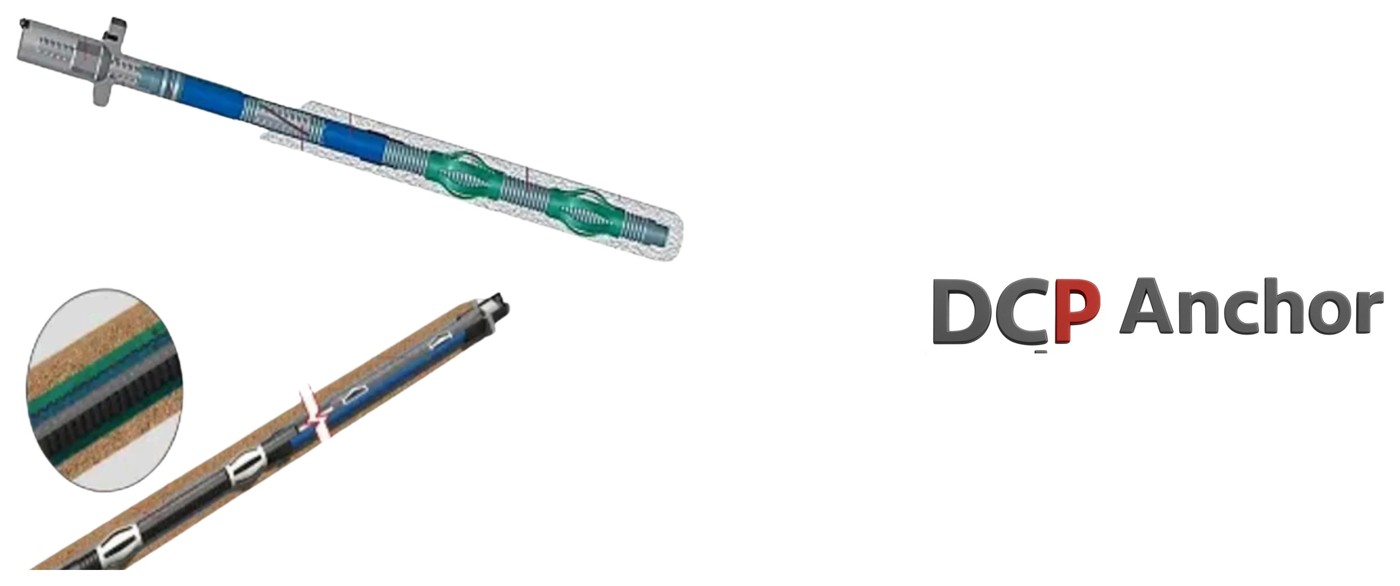
DCP Anchor
Permanent ground anchor with double corrosion protection.
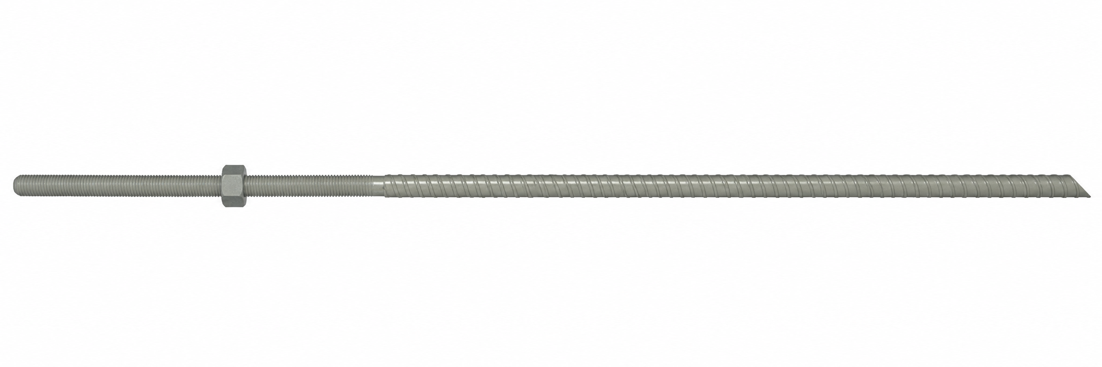
Double Corrosion Protection anchors are permanent ground anchors for long-term structural support. The steel tendon is protected by an inner grout layer and corrugated plastic sheath, with additional grout surrounding the anchor in the borehole. Total anchor length = free length + fixed length + stressing-tail length.
- Double corrosion protection
- Designed for permanent installations
- High load-bearing capacity
- Reliable in aggressive ground
- Factory-controlled protection
- Long service life
- Suitable for stressing and testing
- Reduced maintenance requirements
Technical data
- Anchor diameter
- 32 mm
- Bar grade
- 950/1050
- Fixed length
- Project-specific design
- Free length
- Project-specific design
- Stressing tail
- Project-specific design
- Corrosion protection
- Double Corrosion Protection (DCP)
Applications
- Permanent slope stabilization
- Retaining walls
- Deep excavations
- Bridge abutments and foundations
- Dams and hydropower structures
- Tunnel portals and underground works
- Uplift-resistant foundations
- Marine and aggressive environments
Technical tables
Fully threaded bar
| Property | Unit | Declared value |
|---|---|---|
| Nominal outer diameter | mm | 32 |
| Cross-sectional area | mm² | 804 |
| Nominal mass per metre | kg/m | 6.53 |
| Yield strength | MPa | 950 |
| Ultimate strength | MPa | 1050 |
| Characteristic breaking load | kN | 845 |
| Maximum initial stressing force | kN | 676 |
| Maximum overstressing force | kN | 722 |
Anchor geometry: Total anchor length = fixed (bond) length + free length + stressing-tail length.
| Item | Property | Value |
|---|---|---|
| Coupler | Outside diameter | 60 mm |
| Coupler | Length | 160 mm |
| Coupler | Inside diameter | 32.5 mm |
| Coupler | Material grade | 950/1050 MPa |
| Coupler | Nominal weight | 2.45 kg/pc |
| Dome nut | Outside diameter | 60 mm |
| Dome nut | Length | 50 mm |
| Dome nut | Spanner width | 58 mm |
| Dome nut | Material grade | 950/1050 MPa |
| Dome nut | Nominal weight | 1.40 kg/pc |
| Bearing plate | Width × length × thickness | 180 × 180 × 40 mm |
Anchor-head components and standard/additional accessories (source image).
| Requirement | Definition |
|---|---|
| Anchor length | Fixed length + free length + stressing-tail length |
| Fixed / bond length | To be designed for project ground and grout bond |
| Free length | To be designed for required elastic movement |
| Stressing-tail length | To suit jack, chair and stressing coupler |
| Main bar | 32 mm fully threaded bar, grade 950/1050 |
| Corrosion protection | Double corrosion protection (DCP) |
Anchor-head components and standard/additional accessories (source image).
| Function | Components |
|---|---|
| Load path | 32 mm bar • coupler(s) • dome/spherical nut • 180 × 180 × 40 mm plate |
| Inner barrier | Corrugated HDPE/PVC sheath with factory/inner grout |
| Free-length barrier | Smooth debonding/bond-breaker tube |
| Positioning | Inner and outer centralizers for fixed and free lengths |
| Head sealing | Trumpet • O-ring/seals • protective cap • anti-corrosion compound |
| Grouting | Grout tube and site grout surrounding the encapsulated tendon |
| End protection | Sealed anchor end cap |
Illustrative double-corrosion-protection layer build-up (source image).
| INSTALLATION GUIDEPreparation, Centralizers and Insertion | TS BOLTTUNNEL SAFETY BOLT |
|---|---|
| CONTROL POINT | Use the approved project method statement, lifting plan and inspection plan. Reject or repair damaged sheaths, seals or end caps before the anchor enters the borehole. |
Protective cap filled with anti-corrosion compound and sealed head detail (source image).
| No. | Control stage | Minimum record | When |
|---|---|---|---|
| 1 | Materials and traceability | Bar, coupler, nut and plate certificates; dimensions; heat/batch; component compatibility | Before assembly |
| 2 | Factory/DCP condition | Corrugated and smooth sheaths, factory grout, couplers, end cap, seals; no cuts, voids or leakage | Before insertion |
| 3 | Borehole | Location, angle, diameter, depth, cleanliness and water test where specified | Before insertion |
| 4 | Assembly | Fixed/free lengths, centralizers, grout tube, exposed stressing length and lifting points | Before insertion |
| 5 | Site grouting | Grout ID, mix/batch, flow/density if specified, cubes/cylinders, volume, pressure/return and interruptions | During grouting |
| 6 | Grout acceptance | Required compressive strength achieved before stressing | Before stressing |
| 7 | Stressing equipment | Jack/gauge/load-cell calibration and zero check; reaction frame capacity and alignment | Before testing |
| 8 | Anchor test | Load increments, hold times, displacement, creep, lock-off and acceptance result | During stressing |
| 9 | Head protection | Trumpet engagement, compound fill, O-ring, three screws, injection plug and final seal | After lock-off |
| 10 | Handover | As-built location, serial/traceability, grout and stressing records, non-conformances and approvals | Completion |
The stated bar loads and stressing limits are nominal product values based on the declared 32 mm bar geometry and grade. Actual anchor capacity is governed by the complete system, fixed/free lengths, ground conditions, borehole quality, grout bond, couplers, anchorage hardware, corrosion-protection integrity, installation and testing. Verify by project-specific design, approved method statement and acceptance testing.